The Sun Tracker, Reloaded
Hello!
So, finally I got some time and internet connection to update my blog after such a long time. Actually, I just joined college and moved to city, so I needed some time to settle down.
Moving on!
Remember the Sun Tracker Project I made as high school project which won me 2 national awards?
Well now I thought of working on it further and submit another project report to Indian Institute of Science (IISc) Scholarship program for undergraduate students. Earlier project report was just a plain ol' MS Word document made on a borrowed computer, but this time I had my own laptop and good knowledge of graphic designing and animation to work with. So naturally, this time it was a visual delight to go through the report. Hope that admission officers at IISc also say the same ;)
Here, I'll provide some data I collected with the working model and some illustrations showing the design, structure and circuit diagram of the model.
The basic concept on which the electronic circuit works is as shown below;
When the two oppositely placed sensors are equally exposed, the tracker is in stable state i.e. not rotating. But when one comes under shadow it signals the circuit to rotate the panel.
Actually, the 2-axis sensor looks like this; You can see clearly the sundial kind of effect. In this image light source is at front right side of the sensor as seen by you.
Below image shows the basic schematic of the tracker design as I made it; notice the position of the sensor. A ball & socket type of joint is used which gives full freedom of rotation in two dimentions. Actually, this design, as it was later found, is not stable enough for rough applications. See for instance, in windy weather, fast moving wind will put a lot of strain on the drive belts because the torque (rotating force) on the back side of the panel due to wind would produce a lift force which would be imbalanced on the different halves of the panel.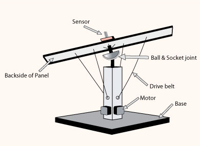
![]()
And this is an image showing the basic, very cheap and fundamental circuit design used in a Sun Tracker. What the IC in this circuit does is to subtract the two values of voltage at oppositely placed sensors on the sensor board, here S1 & S2.
Difference of the voltages with some current amplification is what is used to drive the motor. And the motor is a basic DC type so that when the output voltage (after subtraction by IC) is positive the motor rotates clockwise and when the output is negative the motor rotates in the opposite sense.
For 2-axis rotation two of the circuits are required with 2 motors, or a single motor with a dividing gear. S3 and S4 are part of the 2nd circuit.
e-mail me for more info on this project. If you know anything about Sun Trackers please take some time to share it with me. Thanks! My e-mail address: mridul(dot)nangal(at)gmail.com


4 comments:
Hi Mridul,
Its great to see the kind of cool stuff you are building. I have a 1.8kW solar power system on my roof and wanted to build a tracker for it. I am not keen on any electronics or motors for this (even though I am an hands-on electronics engineer :), I am looking to build a very simple low maintainence system using a bucket of water and a fixed counter weight. So basically, one side of the panels will have a fixed weight which is sufficient to rotate the panel on one axis. The side of the panels will have a bucket with a hole at the bottom and filled with water. I would reset the system to face eastards everyday morning and then and then let it track as the water level reduces in the bucket.
Any thoughts on this?? My email is rajeshpt@yahoo.com.
Thanks,
Rajesh
Hello Rajesh,
Thanks for the appreciation!
Oh Wow! you have 1.8 kW solar power. That's amazing.
Yes, making a tracker for the installation would surely help. The idea is good but I have doubts; even if you are making a bucket-weight kinda system, you'll have to put the panel on an axis, and that takes 60% of work out of an electronic tracker.
Anyway, if you are keen to develop a manual system, which is a kind of see-saw, have you done calculations? Water level in the bucket will not reduce linearly because that depends upon the height of water level in the bucket, as it'll decrease gradually, amount of water coming out will reduce per unit time. And that means weight loss from the bucket is not linear, which will mis-align the panel gradually. A better option would be 'gain of weight' rather than reducing. Place the bucket under a water pipe with a control valve that regulates the flow (in simple words, a tap) and let water drip into the bucket continously, this will ensure linear variation of weight of bucket which you can use.
But as I'll suggest, if you dont want to make electronic circuit, attach a simple low speed DC motor with some gears and feed controlled amount of current to the motor so that it rotates continously, without the need for complex (relatively) sensing mechanism.
Good luck, and tell me more about the 1.8 kW system, where did you get it and what you do with it and how much it costs etc etc.
Best Regards,
Mridul Kashatria
I hope you are still monitoring this site!
I'm building some parabolic solar troughs for heating and have been looking at ways of building a 2 axis solar tracking device.
What I am interested in knowing, are some more details on that schematic.
1) What is the ohms of those resistors?
2) What type of sensors are those? (could you be more specific?)
3) Are all transistors created equally? If not, what type did you use?
4) Can I get these parts at Radio Shack, or do I need a more specialized store?
Thanks so much!
John
Hi Sir
You have great work in your blog.
Keep it up.
You know? You can build a single solar panel or you can build an entire array of panels to power your whole house.
Post a Comment